Developing an Arduino based Smart Motors
Developing Arduino-based smart motors involved multiple iterations to find the right materials and production process. We started with Milan's smart motors as our base idea, which had a display and navigation button, but we wanted to make them locally.
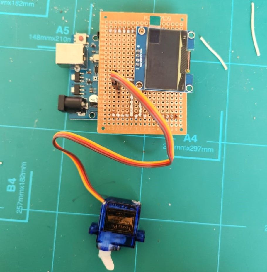
In our first circuitry attempt, we used a 1.3-inch OLED display, Arduino Uno, and push buttons for navigation. However, the display felt too small and not user-friendly, especially for students. Another challenge was sourcing materials and finding a microcontroller that's easy to work with and readily available.
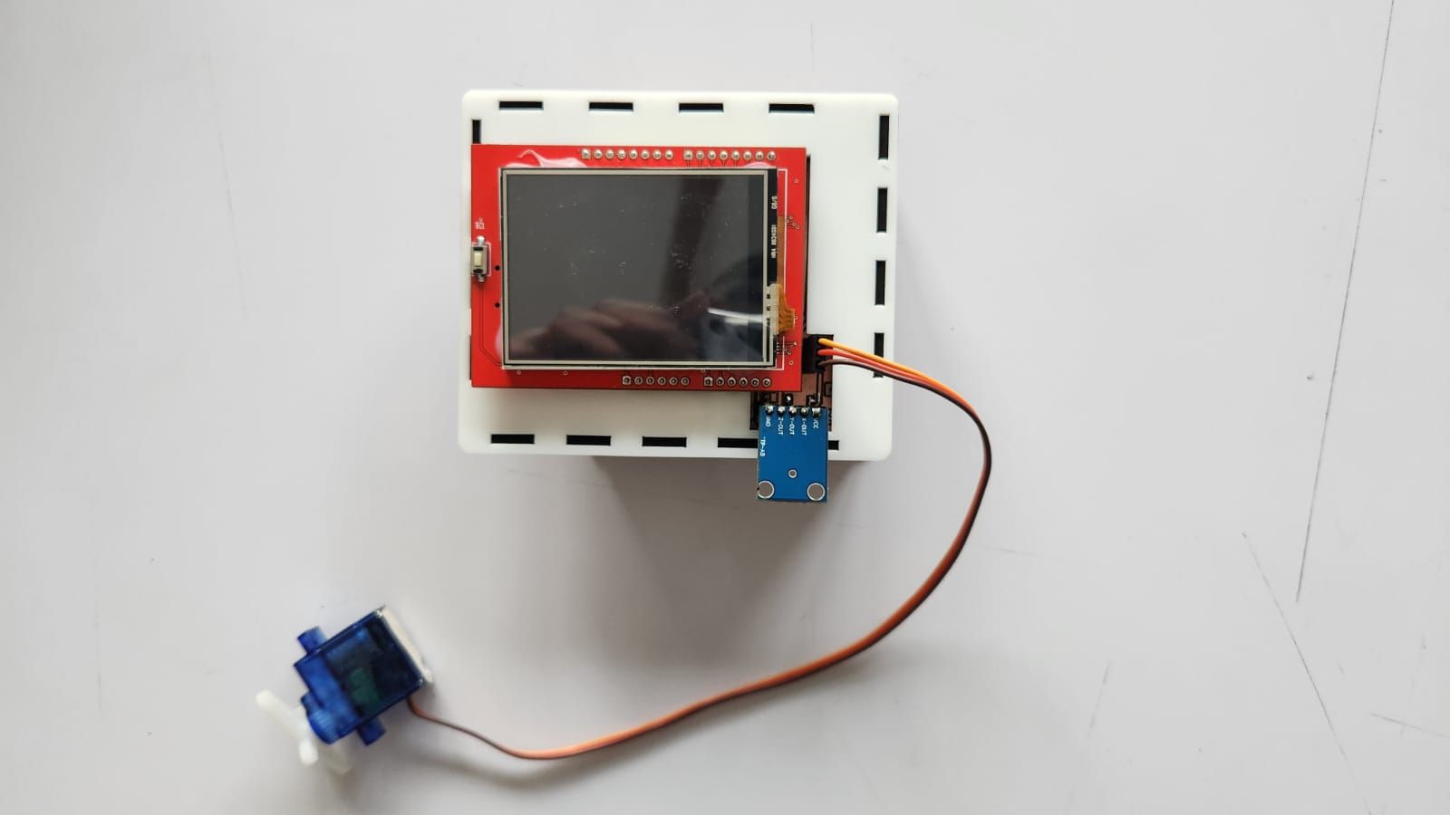
We tried different displays, testing a large non-touch display initially, but eventually chose a touch display. This solved the screen size problem and eliminated the need for physical buttons. With a touch screen, we could add as many buttons as needed. We carefully studied the TFT datasheet to ensure proper connections and finalized it as our display choice.
One significant change we made was creating our own sensor modules, which are not soldered onto the PCB. This idea came from teachers and students in our WIO terminals classes who were curious about the sensors. We added a female header connected to Arduino's read pin, so anyone could easily add their own sensor to our design. We made sensor modules for light detection (LDR) , variable control (Potentiometer), and motion sensing(Accelerometer).
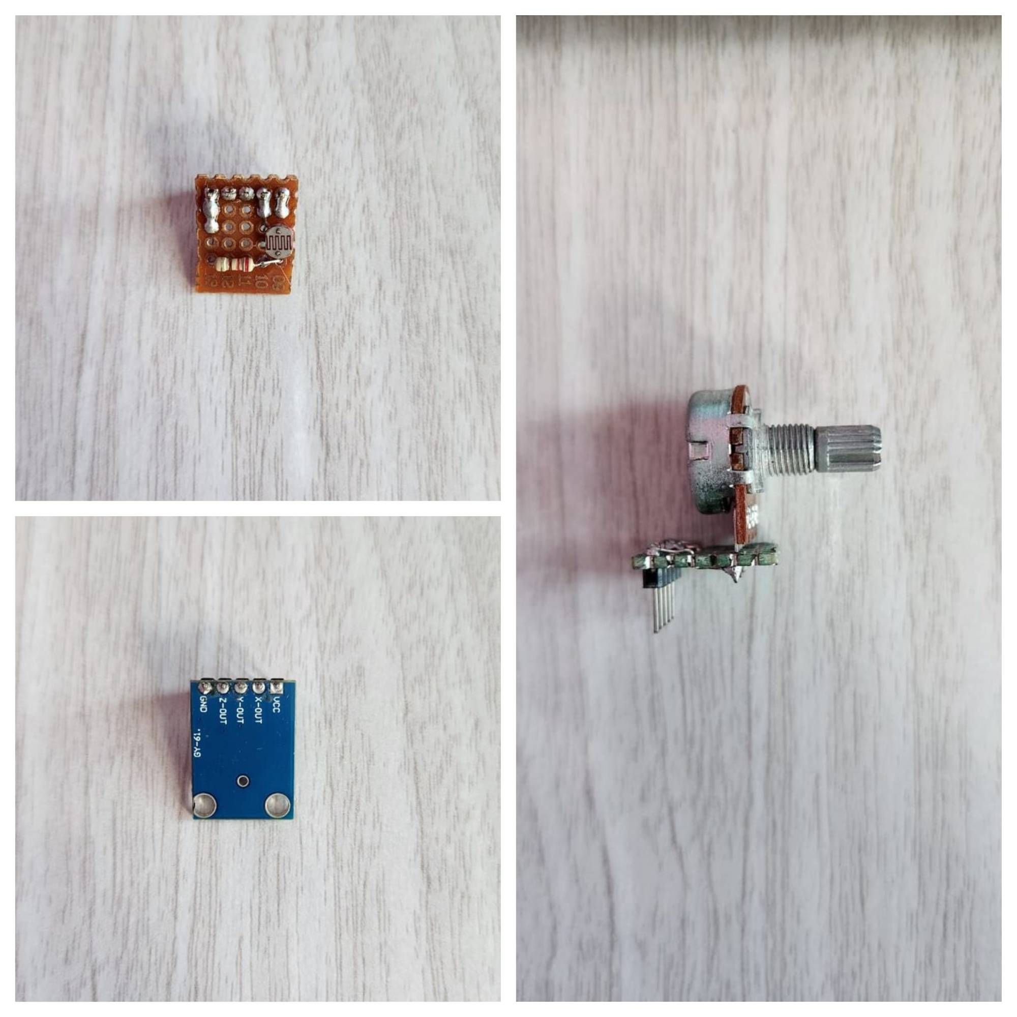
To test our concept, we created simple prototypes using a matrix board and jumper wires for the circuitry. Everything worked well, including the touch functionality and sensors. Best of all, we could find all the components we needed locally.
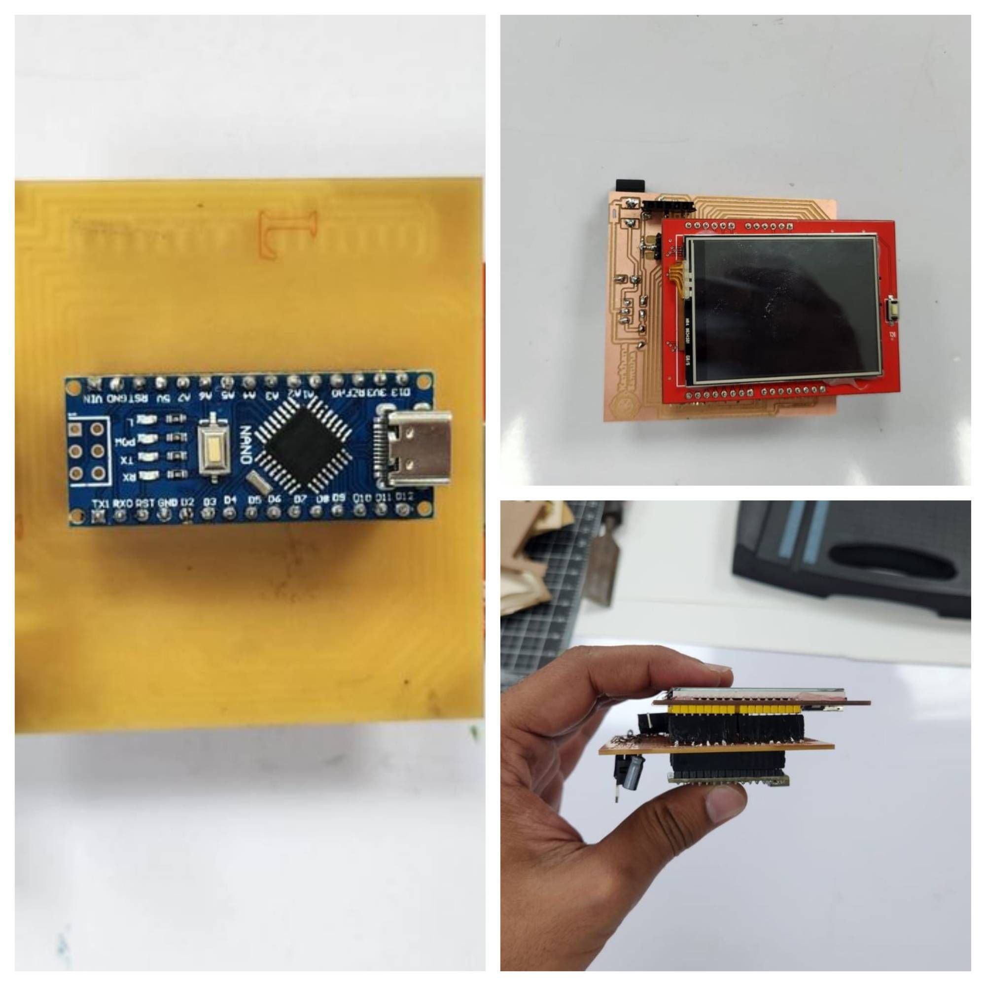
For the final version of our smart motors, we chose an Arduino Nano for its small size, Type-C charging and data transfer, modular sensors, SG 90 servo motors, and a 2.4-inch TFT touch display.

To manufacture the PCBs and casings, we partnered with FabLab Nepal. We made sample PCB designs and successfully produced them. However, the PCBs were a bit bulky because we could only make single-layer ones.
In our last iteration, we realized the importance of ensuring the smart motors would still work if the power went out. So, we added a battery connection to the circuit and incorporated it into the final model.
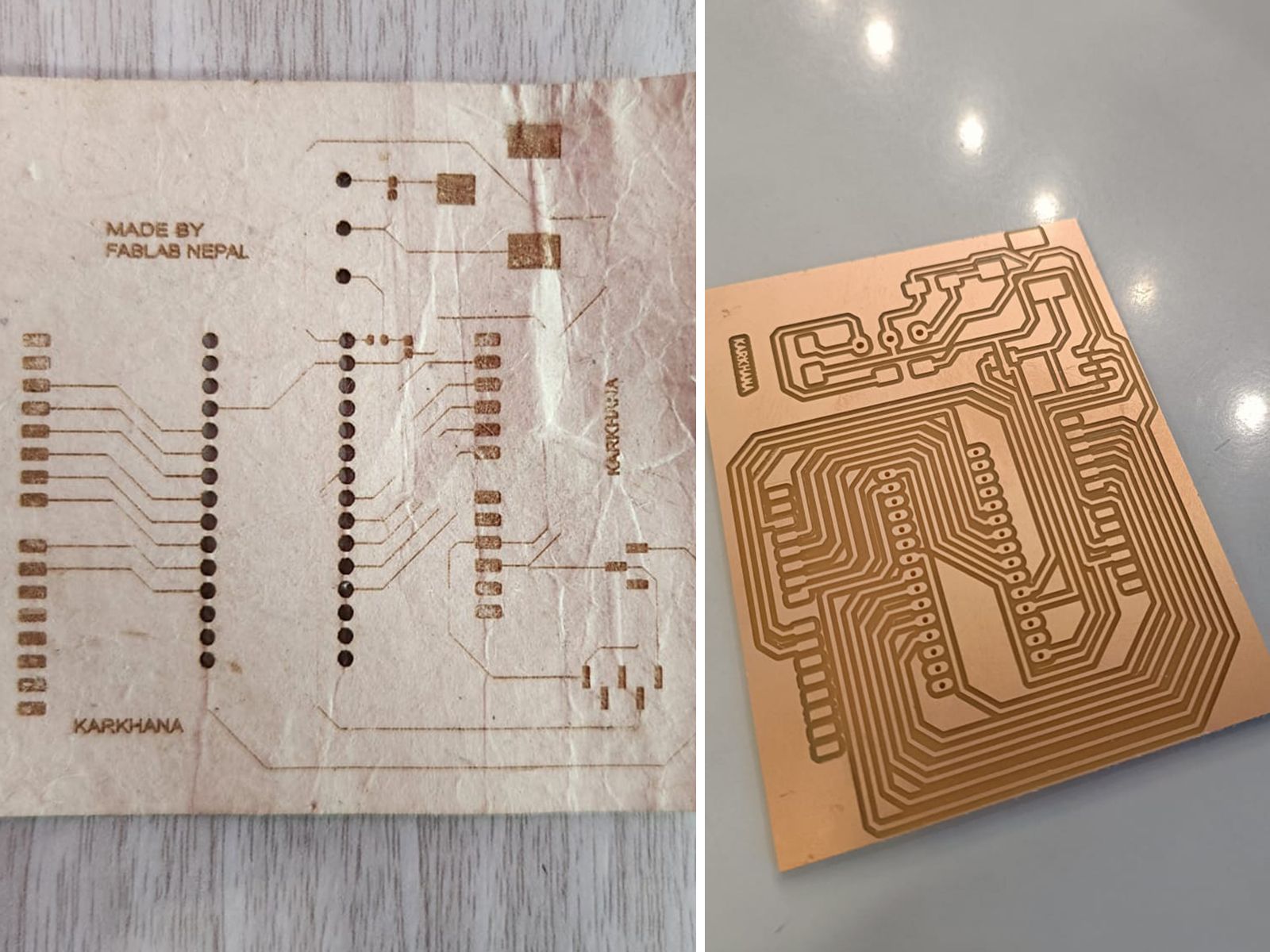
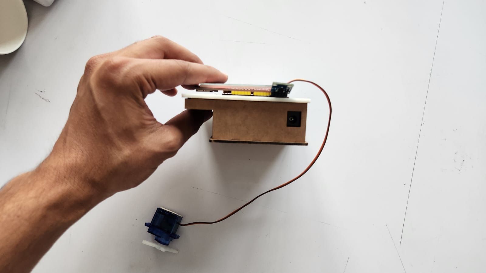
After completing the PCBs, we focused on designing the casings. We wanted them to be modular, so we decided to use MDF boards for the cases.
During initial testing, we encountered various issues like the touch not responding, unreliable training models, and uncalibrated sensors. However, after multiple rounds of fixing and adjusting, we managed to reduce these problems to an acceptable level.
